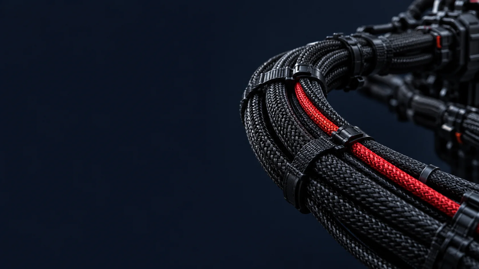
Strain relief transfers pulling, bending and vibration loads away from crimped or soldered joints into the cable jacket and supporting structure. Wire routing defines the harness path, fixing points, bend radii and separation before assembly. Design them together: a secure clamp cannot rescue an impossible connector exit, and a neat route cannot protect a terminal carrying an unsupported cable load. This guide turns those decisions into drawing requirements for a wire harness.
LAPP explains the load-transfer principle: the supporting structure absorbs external forces rather than passing them to the contacts. The recommendations below apply that principle to harness design reviews; component limits still come from the selected manufacturer's documentation.
Make the decision from three viewpoints
- Design: identify what pulls, moves or vibrates, where the enclosure gets hot, and which circuits need separation. Check the installed route with connectors mated and service access available.
- Manufacturing: turn that route into repeatable branch lengths, connector orientations and support locations. Confirm that sleeves, boots and backshell parts can be installed in the planned assembly sequence.
- Procurement: buy against defined cable and accessory part numbers. Ask how proposed substitutes change outside diameter, bend limits, clamp fit or tooling before accepting them.
Resolve those questions in the wire harness RFQ DFM checklist. Treat an undefined support or bend as an open drawing item, with an owner and an approval decision.
Failure modes, causes and design countermeasures
This is a review checklist of possible mechanisms, not a diagnosis or a claim about failure frequency. The manufacturer references in the following sections support the load, abrasion, fastening, interference and temperature considerations.
| Failure mode | Possible routing-related cause | Design countermeasure |
|---|---|---|
| Wire breaks at a crimp | External loads reach the termination | Provide jacket or bundle support; check the terminal application specification separately |
| Breakage behind a connector | Bending concentrates at an unsupported exit | Choose a compatible boot or backshell and a feasible exit direction |
| Jacket abrasion | Movement against an edge or adjacent structure | Reroute, restrain movement and specify edge protection or sleeving |
| Insulation crushed by a cable tie | Excessive installation tension | Define the tie and controlled installation setting; inspect for damage |
| Power-to-signal interference | Noise coupling along adjacent routes | Separate routes and specify crossings and shielding to the equipment requirements |
| Insulation aging near a heat source | Temperature exposure incompatible with the selected material | Move the route or select suitable materials; verify operating temperatures |
Choose a strain-relief system with a defined load path
Overmolded rear housings integrate support at the connector-to-jacket transition. Molex describes overmolded strain relief as reducing mechanical stress on wires and terminals. Specify the cable, connector, material and geometry together; our overmolding capability page is a starting point for that manufacturing discussion.
Heat-shrink systems and strain-relief boots need a compatible attachment arrangement. TE documents backshells using heat-shrink boots or cable clamps for strain relief. Do not credit an unspecified sleeve with a retention load: name the parts and the assembly method, then define the required verification.
Cable clamps support the harness against a structure; specify their grip range and mounting. Cable glands can combine enclosure entry, retention and sealing, as described in LAPP's gland overview. Select against actual cable dimensions and installation instructions. For an unjacketed bundle, specify a suitable bundle-support arrangement rather than assuming a gland will grip or seal individual wires correctly.
Use the cable datasheet's OD multiplier
Minimum bend radius is a product requirement, not a universal harness rule. The public HELUKABEL JZ-500 / OZ-500 datasheet, page 1 expresses it as 4 × outer diameter for fixed installation and 7.5 × outer diameter for flexible use. Those values illustrate the notation and the distinction between use conditions; they are not permission to apply either multiplier to another cable.
Record the selected cable's OD, minimum radius, operating condition and datasheet revision on the drawing. Do not infer a repeated-motion lifetime from a flexible-use radius alone. Request motion-specific data where needed. Conductor gauge also does not establish finished cable OD; use the wire gauge selection guide for electrical sizing, then check the chosen construction's mechanical dimensions.
Hypothetical example: an 8 mm cable and a 30 mm wall gap
Assume a cable OD of 8 mm and a selected datasheet requiring a static bend radius of 4 × OD. The minimum is 4 × 8 mm = 32 mm. These are assumed design inputs, not a customer case or the dimensions of a specified HELUKABEL part.
Also assume the cable exits straight toward a wall 30 mm away and must turn 90 degrees before reaching it. Even generously treating all 30 mm as available bend radius, 30 mm < 32 mm: the route fails this preliminary check by 2 mm. Cable thickness, a required straight exit and tolerances consume additional clearance; the CAD check must use the manufacturer's radius measurement convention.
Consider a compatible right-angle backshell or change the connector orientation and routing direction. Recheck the whole exit envelope afterward. A right-angle part is a proposed geometry change, not an automatic pass.
Coordinate connector exits, ties and fixing points
TE's backshell range includes straight and 90-degree clamp arrangements. Specify the selected exit direction and clocking relative to an enclosure datum. Include the backshell envelope, mating access, support location and any required straight section. Avoid a drawing that depends on the assembler pulling a branch sideways to make it reach.
Set tie type, location, spacing and installation tension in the drawing or referenced work instruction. Do not invent a common spacing for every bundle. HellermannTyton's cable-management guidance describes controlled installation tools as helping prevent overtightening and cable damage. Its guidance also covers clips, mounts and protective conduits for wiring exposed to vibration and abrasion.
Review support locations around breakouts and connector exits, and inspect the supported bundle for pinching or rubbing. Keep the routing review alongside the termination process: see crimping and soldering capabilities. Adding support does not establish that a joint was correctly made.
Separate power and signal; review heat exposure
Schneider Electric's ATV71 Modbus guidance recommends separating communication and power cables and crossing at right angles when a crossing is necessary. Apply this as a routing review principle; derive actual separation, shielding and grounding requirements from the equipment and interface documentation. Avoid running sensitive signal branches alongside noisy power branches merely because one bundle is easier to tie.
Mark hot zones on the installation drawing. HELUKABEL's aging-test explanation identifies thermal aging as a cable-life consideration. Check the cable and support materials against the temperature they will experience, and document any rerouting or protective measure for validation. Do not assign a service-life claim from a jacket material name alone.
Make the route buildable and inspectable
Include routing geometry in the harness drawing and translate it into a routing board or form board. Panduit's harness-board accessories illustrate fixtures for wire retention, corners and breakouts. Use them to reproduce the approved layout while respecting cable bend limits.
For first-article inspection, compare branch lengths, connector clocking, support positions and bend geometry with the drawing. Check fit in the intended enclosure or a representative installation fixture; a flat board alone cannot establish three-dimensional clearance. Define electrical checks and any required retention, flex or vibration validation separately through the testing review.
IPC describes IPC/WHMA-A-620 as covering materials, methods, tests and acceptance criteria for crimped, mechanically secured and soldered interconnections and related harness assembly activities. Reference the agreed revision and class as a workmanship acceptance standard, alongside the product-specific drawing requirements.
What to include in a Philippines factory RFQ package
For a harness RFQ to XUDONG in Cavite, Philippines, make these items explicit so the manufacturing review can resolve questions before the first build:
- Controlled definition: harness drawing, revision, BOM, pinout and installation model or dimensioned enclosure views.
- Cable limits: exact part number, OD and tolerance, bend-radius source, fixed or moving use, and environmental requirements.
- Termination geometry: connectors, backshells, boots, overmolds, exit direction, clocking and access constraints.
- Routing controls: branch lengths and tolerances, fixing locations, tie settings, edge protection, separation and heat exclusions.
- Acceptance plan: workmanship criteria, first-article fit checks, required tests, conditions, sampling and records.
- Build control: prototype and production quantities, approved alternates, substitution approval and label locations linked to the labeling and traceability plan.
Submit the package through the RFQ page, or use the wire harness blog hub to work through related design questions.
FAQ
Is heat shrink enough for strain relief?
Only when the specified heat-shrink system and its attachment meet the required retention and bending conditions. Identify the parts, installation method and verification; a sleeve by itself does not establish an accepted load path.
What minimum bend radius should a harness use?
Use the selected cable manufacturer's requirement for the actual operating condition. The 4 × OD example here is conditional. A different construction or moving application requires its own data and routing review.
How far apart should cable ties be?
Define spacing and tension for the particular bundle, support structure and service conditions. Put the approved arrangement on the drawing or referenced work instruction, and check it at first article.
Can power and signal wires share a harness?
Review them by circuit and interface requirements. Specify separate branches or paths where needed and define crossings and shield terminations. A shared harness designation does not establish acceptable electromagnetic performance.
Does a terminal pull test validate the complete route?
No. A terminal pull result addresses the tested termination under its stated conditions. Complete routing also needs fit, support and clearance checks, plus any application-specific motion or environmental validation in the agreed test plan.